|
Earthquake Shaking – Building Contest and Shake
Table Testing Activity 1 L. Braile, braile@purdue.edu, web.ics.purdue.edu/~braile
|
(Posterboard Buildings, May, 1999; revised, March 2003, October 2003, updated
December, 2005, October 2012) |

Objectives: Explore earthquake hazards and damage to buildings by constructing model buildings and subjecting the buildings to ground vibration (shaking similar to earthquake vibrations) on a small shake table. The buildings are constructed by of two- or three-person teams of students or workshop participants. After construction, the buildings are tested by subjecting them to earthquake shaking to see which designs and constructions are successful. Comparison of the results of the building contest with photographs of earthquake damage is used to reinforce the concepts of building design and earthquake risk.
Materials:
· Posterboard (lightweight posterboard; note: there is a difference in quality and therefore strength of lightweight pasteboard; the best posterboard has one smooth, almost glossy side and on dull side; lightweight posterboard can be purchased at most bookstores, convenience stores, Wal-Mart and K-Mart.)
[1]  Last
modified October 18, 2012
Last
modified October 18, 2012
The web page for
this document is:
http://web.ics.purdue.edu/~braile/edumod/building/building.htm
Partial funding for this development provided by the National Science Foundation.
ã Copyright 2004-12. L. Braile. Permission granted for reproduction and use of files and animations for non-commercial uses.
4 – 8 x 8 cm squares (floors)
12 – 1½ x 10 cm strips (uprights)*
12 – 1½ x 15 cm strips (reinforcing)*
1 – 30 x 8 cm (cut and use as you wish)
· Scotch Tape (2 cm or 3/4” wide) 100 cm length (Plan accordingly!)
· Scissors
· 30 cm ruler
Rules:
· Building must be:
At least 30 cm high
at least 3 stories
no central post or uprights (so that weights can be placed on floors)
· Materials are limited (realistic)
· Complete construction in limited time (realistic)
Design:
· Note importance of shear or diagonal support. This concept can be illustrated (and explained) using the shear wall model from Seismic Sleuths (FEMA/AGU, 1994; Figure 1). One can also build model walls using short strips (1½ x 10 cm and 1½ x 14.4 cm) of 1/16” thick mounting board, or other similar materials such as popsicle sticks, and magnets or mounting putty for joints. Without diagonal bracing, the model wall is relatively strong for a static, vertical load. However, a horizontal load or shaking causes the wall to collapse. With the diagonal bracing (shear-support) installed, the wall is much stronger and more resistant to shaking.
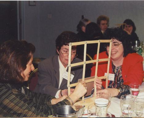
Figure
1. Experimenting with the Shear Wall
(Seismic Sleuths activity).
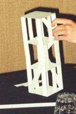
· Simple, rectangular building designs are effective (Figure 2). Many design options, particularly for the bracing, are possible.
Figure
2. A partially completed lightweight
posterboard model building.
Testing:
· Buildings are tested on the horizontal motion shake table (Figure 3). Tape the base of the building to the base plate of the shake table. We choose the direction to orient the building.
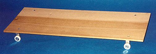
Figure 3. A simple, horizontal
motion shake table. Wheels are nylon
cabinet or drawer wheels and are attached to the board with “L” brackets,
machine screws and nuts.
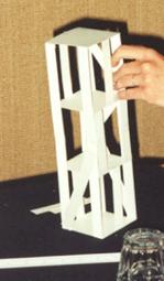
· Add masses to the floors and roof of the building (Figure 4). Masses should be about 30 to 80 g each. Begin testing with small masses. Steel washers of 3-4 sizes make convenient and effective masses. Tape washers to floors and roof or use small plastic spring clips available at hardware stores or in hardware departments of Wal-Mart and K-Mart.
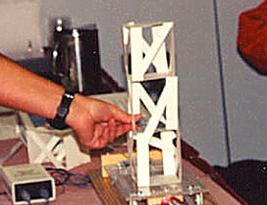
Figure 4. A model building on a
shake table. Weights (steel washers) are
attached to each floor and the roof.
Small (5-g) horizontal accelerometers are attached to the shake table
and to the top of the building. The results
of shake table testing (acceleration versus time of the shake table and the top
of the building as the shake table is moved back and forth) can be monitored on
the computer screen or projected using an LCD projector for everyone to see.
· Shake building at three frequencies – low, medium and high – and at three amplitudes – low, medium and high. An accelerometer on the base plate can be used to quantify the shaking and make comparisons between the testing of different buildings more consistent. A second accelerometer can be attached to the top of the building to observe amplification and resonance effects. Small, relatively inexpensive accelerometers, an analog to digital interface for the accelerometers (Serial Box Interface or LabPro), and software (LoggerPro) for the interface are available at Vernier Software (www.vernier.com) or other vendors of “probeware”. High School or College physics departments often have Vernier or similar equipment so you may only need to obtain the accelerometers.
·
In our experience, using the instructions and
materials described here, it will usually be possible for most buildings to
survive the shaking using small masses (30-50 g). However, few buildings with these materials
will withstand strong (about 1 g, 1 g is the acceleration of
gravity which is 980 cm/s2 or 9.8 m/s2), high frequency
(about 10 Hz), shaking with larger masses (50-80 g).
Interesting resonance and amplification effects will be visible for some
frequencies and amplitudes of shaking.
· If your shake table is large enough (a convenient size is about 16 x 50 cm), you can attach and test two or three buildings at the same time which provides an interesting comparison of building responses.
· After the initial testing, it is possible to illustrate specific design issue/problems with model buildings that were successful. For example, you can create the "soft first story" problem by reducing the shear support in the first story of the building. Sometimes buildings are damaged by a mainshock earthquake and then further damaged or destroyed in an aftershock. Also, poor quality construction or mistakes made in construction can result in specific weak elements of a building. These situations can be simulated in a model building by weakening an upright or a joint by cutting or partially cutting the posterboard material or tape. Other building design and construction variations, such as very rigid or very flexible buildings, can be specifically built and tested. Comparing the responses and failure levels of these structures with the original designs that were successful is an excellent method of reinforcing the principles of effective building design and earthquake hazards related to structures.
· If time permits, students can construct a second set of buildings that benefit from the lessons learned in the first building contest and shake table testing.
· An excellent videotape on earthquakes that includes a segment on building design and shake table testing of a model building (using Legos) to show the importance of shear support is "Seismic Sleuths," Discovery Channel (www.discovery.com).
To view corresponding photographs of earthquake damage to buildings and other structures (for comparison to the lessons learned in shake table testing of the model buildings) and other information on earthquake hazards see:
at: http://web.ics.purdue.edu/~braile/indexlinks/educ.htm (use Quick Links), and/or:
2. A Power Point presentation (eqdamage.ppt) with some of the earthquake damage photographs (Figure 5) contained in the above online pages (available at: web.ics.purdue.edu/~braile, click on “Workshops” in the Quick Links).
Also note the significant building failures and risk represented by falling objects (on the exterior or within buildings) and poor foundations and liquefaction.
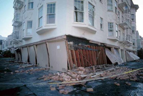

Figure 5. “Soft” or weak first
story failure of a four-story building in San Francisco damaged by the October,
1989 Loma Prieta earthquake. In this
case the weak story is caused by reduced shear wall strength and lack of
diagonal bracing related to constructing parking garages (note garage doors) in
the first story of the building.
References:
Boss
Lite resonance model, http://www.iris.edu/hq/resource/boss_lite_building_resonance.
Earthquake
Shaking, two-Story House, http://www.abag.ca.gov/bayarea/eqmaps/fixit/videos.html.
FEMA/AGU, Seismic Sleuths - Earthquakes - A Teachers Package on
Earthquakes for Grades 7-12, American Geophysical Union, Washington, D.C.,
367 pp., 1994. (FEMA 253, for free copy, write on school letterhead to: FEMA,
Levy,
Matthys and Mario Salvadori, Why Buildings Fall Down, W.W. Norton & Co.,
Levy,
Matthys and Mario Salvadori, Why the Earth Quakes, W.W. Norton & Co.,
Quake Catcher Network (accelerometers), http://qcn.stanford.edu/.
Salvadori,
Mario, Why Buildings Stand Up, W.W. Norton & Co.,
Vernier Software (accelerometers), http://www.vernier.com/.