|
|

HANDHELD SEISMOMETER
(L. BraileÓ, November, 2000)
http://web.ics.purdue.edu/~braile
![]()
Introduction:
The handheld seismometer is designed to illustrate concepts of seismometry (sensing and recording the vibration or shaking of the ground generated by propagating seismic waves) and to be used as a simple seismometer for educational demonstrations and activities in seismology. The handheld seismometer is designed to be as visual and inexpensive as possible to best meet these objectives. Modifications could improve the sensitivity and performance characteristics of the seismometer, probably at the expense of simplicity and cost.
Theory:
Most seismometers detect ground motion using a mass which is suspended in some fashion by a spring. When the ground moves (say in an up and down or vertical motion), the seismometer's frame also moves, but the mass tends to remain relatively steady because of inertia. The relative motion of the mass with respect to the frame (and thus the ground) is then converted to an electrical signal (voltage variations with time) using a capacitor plate, a galvanometer or a magnet and coil assembly. Seismometers are usually sensitive to one component (direction) of ground motion (vertical or horizontal) and thus three components are used to completely characterize the seismic signals. A typical vertical component seismometer design is illustrated in Figure 1. Difficulties in understanding the theory and operation of such a design and of working seismometers are caused by: 1) the usual complexity of a modern, sensitive electromagnetic seismometer, 2) the difficulty of experimenting with the construction and components of the sensor, 3) the confusion caused by the fact that, although it appears in demonstrations (by physically moving the mass up and down) that it is the mass that is moving, it is actually the frame that moves and the mass tends to remain steady, 4) difficulty in understanding the electromagnetic sensor (transducer) theory and operation, and, 5) seismometers are usually expensive instruments enclosed in a case to improve performance and protect the mechanism, making it difficult for students, educators and other non-seismologists to obtain and experiment with the instrument.
The handheld seismometer solves some of these difficulties by being simple, visible and inexpensive to build. Principles of seismometry, including electromagnetic sensing using a magnet and coil, simple harmonic motion of the spring and mass system, damping and recording the seismic signal, can be easily demonstrated. One of the most effective demonstrations, is to simply hold the seismometer in one's hands and then "shake it" by moving the base up and down and noting the output. The seismometer can also be used on a tabletop for manual experimentation.
The magnet and coil sensor operates by measuring the change of the magnetic field by the amount of voltage produced in the surrounding coil. The sensor characteristics (primarily its sensitivity) are controlled by the strength of the magnet, the number of turns of wire in the coil and the distance of the magnet from the coil. Once the sensor is constructed, it is easy to demonstrate that the electrical output of the sensor is approximately proportional to the velocity of motion of the mass with respect to the coil. Alternatively, a more effective way to introduce the electromagnetic sensor used in many seismographs is to use a magnet and coil apparatus (Figure 2). One can use the magnet and coil to illustrate the generation of a current or voltage in the coil that is caused by the motion of a magnetic field. Connect the ends of the magnet wire from the coil to the simple seismometer amplifier circuit and the Vernier Serial Box Interface or to a digital multimeter. Hold the magnet inside the coil. Note that if the magnet is held steady, the output of the electrical signal is near zero (or a constant). When the magnet is moved up and down, a voltage is produced. When the magnet is moved rapidly, a larger voltage is generated. Note that moving the magnet up and down within the coil produces alternating positive and negative signals representing the relative motion of the magnet as compared to the coil.
Constructing the Handheld Seismometer:
Construction details and parts are provided on the attached diagram (Figure 3) and list. Figure 4 is a photo of a completed handheld seismometer.
Using the Handheld Seismometer:
The seismometer can be connected to a recording device in a variety of ways. The amplifier circuit and Vernier SBI (see option number 4 in the "viewing the output signal" section on the parts list, Table 1) is recommended because it provides a visual output of a seismogram on a computer. One can even save the seismograms for later use and for comparison of different shaking sequences. The computer display also aids in developing understanding of data acquisition and analysis concepts. An effective sequence is:
1. Hold the magnet assembly inside the coil to show that the output signal is not directly related to displacement (position in a vertical direction) but to relative motion (actually approximately proportional to velocity) of the mass with respect to the coil. Alternatively, use the separate magnet and coil assembly and procedure (described above) to illustrate the electromagnetic coupling.
2. With the mass suspended from the spring (as shown in Figure 3) and no oil in the container (no damping), cause the mass to move up and down to illustrate simple harmonic motion. Note that here is a "natural frequency" of the oscillation. Measure the period (1/frequency) of oscillation and note the sinusoidal characteristics of the signal.
3. Repeat the steps in number 2 with oil in the container for damping. This is the standard operating set-up for the seismometer.
4. Illustrate an incoming seismic wave and movement of the base (normally attached to the ground) by vibrating the seismometer vertically in your hands. Experiment with a "single pulse" input and a longer duration, more complex input (similar to the series of seismic waves produced by an earthquake source and wave propagation effects through the Earth from the source to the seismograph). See attached sample output of the handheld seismometer, Figure 5.
The handheld seismometer could be placed on the ground or floor to record small ground motion from nearby footsteps, or local seismic noise (such as generated by traffic) or weight drop experiments. However, several factors reduce the effectiveness of the handheld seismometer in this application. These factors include: the relatively low sensitivity of the seismometer; the high frequency of typical nearby sources, particularly on a concrete floor; the damping of the seismometer (which has positive effects as described above) which reduces the sensitivity, particularly for high frequency (³ 10 Hz) signals; and a high frequency resonance (unstable oscillation) of the suspended spring-mass system which is caused primarily by horizontal shaking.
To illustrate the recording of different size signals (different levels of ground motion), hold the seismometer in your hands and move it very slightly upwards. Next, move it moderately and then significantly upward. The three different sized motions of the seismometer base should be visibly distinct and will produce three different sized output pulses. Note that the seismometer output is proportional to the size of the input shaking. Because of this characteristic, the output of the seismometer (a seismogram) can be used to determine the level of ground shaking of the location of the seismometer. Stronger shaking will be generated by larger magnitude earthquakes. The level of shaking at a particular location is also controlled by the distance of the seismograph from the earthquake.
The handheld seismometer can also be used to illustrate common data recording principles. Note that while holding the handheld seismometer as steady as possible, there is still some shaking and therefore a small signal on the output record. Because there is no specific source (intentional shaking of the seismometer or earthquake–generated ground motion) during this time interval, we consider the output signal to be background "noise." Note that a small tap (a specific source of shaking) on the base of the seismometer may not produce a signal that is visible above the noise that is being continuously recorded. Because of the presence of background noise on the seismograph, small signals or signals from distant earthquakes are sometimes not visible on the seismogram because amplitudes (levels of shaking or height of the signal on the seismogram) of the signal may be smaller than the noise level. Furthermore, the presence of background noise encourages seismologists to find relatively quiet (low background noise) sites for locating seismographs. Sometimes ground shaking is too large to be accurately recorded by a seismograph. This situation can easily be illustrated with the handheld seismometer by moving the base rapidly by a large impulse upwards. If the motion is large enough, the suspended mass will hit the top or bottom of the container or the recording equipment will "saturate" because a voltage that is too large to be recorded by the interface (analog to digital converter) or recording software is generated. In this case, the top (or bottom, or both) of the recorded signal will be truncated or "clipped." When the signal is clipped, the maximum amplitudes of the ground shaking will not be accurately recorded, and the signal will be distorted in the time interval where clipping occurs. Both the noise and clipping problems, from too small or too large levels of ground motion, occur commonly in actual recordings of earthquakes by seismographs.
5. Demonstrate the components of a seismograph: mass and spring that sense the ground motion; magnet and coil sensor that converts the relative motion into an electrical signal that can be recorded; amplifier; digitizer (computer interface, Vernier SBI); recorder (computer and software). Note that an absolute time base, usually provided by an accurate chronometer or clock synchronized with universal time, is missing from this assembly. Such an absolute time base is usually included in a research-quality seismograph to provide earthquake monitoring capability.
Viewing the Output
Signal:
A visual record or permanent recording of the output can be accomplished by a variety of methods including:
1. Directly to a strip chart recorder.
2. Directly to an oscilloscope.
3. Connect to a digital voltage meter (VOM; also called a multimeter or volt meter). Digital display will display movement and alternating positive and negative voltages.
4. An inexpensive and effective method to view the output signal of the magnet and coil assembly or the handheld seismometer is to utilize an amplifier circuit and an analog (with needle and dial scales; use 5 volt DC scale) multimeter. The amplifier circuit (Figures 6 and 7; Table 2) can be constructed (in about one hour after all parts are obtained; wire cutter/stripper and small needle-nose pliers are useful, although not required for assembly) using readily available parts for less than $20. An analog multimeter (or VOM or volt meter) can be purchased for less then $20. The output of the magnet and coil or handheld seismometer is very visible from movements of the needle on the multimeter (the DC offset feature of the amplifier circuit centers the needle, when there is no motion and therefore no signal from the magnet and coil, at about +2 volts). Motion of the magnet relative to the coil causes the needle to move back and forth on the multimeter scale. Small velocity motion of the magnet produces small deflections of the multimeter needle. Large velocity motion produces large deflections of the needle. Photographs of the amplifier circuit are provided in Figures 8 and 9.
5. Through amplifier interface circuit (see Simple Seismograph description; the amplifier interface circuit used in the Simple Seismograph activity is nearly identical to the amplifier and DC offset circuit that is described here) and Vernier Serial Box Interface (SBI, digitizer) to Vernier data logger software (LoggerPro) on a Mac or Win/DOS computer. Approximate costs are electronic circuit, $25; SBI, $100; software, $40. (See sample output using this method, Figure 5).
References (additional information on seismometers can be found in the following references):
Bolt, B.A., Earthquakes and Geological Discovery, Scientific American Library, W.H. Freeman, New York, 229 pp., 1993, (Chapter 3 on seismographs).
Bolt, B.A., Earthquakes,
(4th edition), W.H.
Milne, J. and A.W. Lee, Earthquakes, (7th edition), P. Blakiston's Son &
Co.,
Nova videotape: Earthquake! (~11:50-12:40 and ~19:15-20:15 minutes and seconds into the program)
http://wwwneic.cr.usgs.gov/neis/seismology/keeping_track.html (How a seismograph works).
http://wwwneic.cr.usgs.gov/neis/seismology/history_seis.html (Early history of seismometry).
http://cse.ssl.berkeley.edu/lessons/indiv/hs/Seismograph.html (Build your own seismograph).
http://www.freeweb.pdq.net/headstrong/Seis.htm (Building your own seismograph).
http://www.seismicnet.com/equip.html (Build your own seismograph).
Table 1. Handheld Seismometer Parts List(1)
|
Item |
Number |
Description |
Approximate Price |
|
1. |
1 |
Spring (Servalite #59, Ace Hardware)(2) |
$1.65 |
|
2. |
2 |
5" x 1/4"(3) Eyebolts ($0.59 each) |
$1.18 |
|
3. |
4 |
1/4" nuts ($0.04 each) |
$0.16 |
|
4. |
1 |
Wood block ~ 25 cm long(4); 2 x 4 or 1" thick shelf board |
$0.50 |
|
5. |
1 |
Clear plastic container (Anchor Hoching Klear Stor, 236 ml (8 oz), cylindrical container, ~ 11 cm high by 5.5 cm diameter, with white plastic cap, available at Target)(5) |
$1.14 |
|
6. |
2 |
40 cm long 1/2" inside diameter PVC pipe(6) |
$0.35 |
|
7. |
1 |
11.5 cm long 1/2" inside diameter PVC pipe |
$0.06 |
|
8. |
2 |
1/2" PVC 'T' joints ($0.39 each) |
$0.78 |
|
9. |
2 |
1/2" PVC 'Elbow' joints ($0.29 each) |
$0.58 |
|
10. |
1 |
Magnet wire (#278-1345, Radio Shack, 3 rolls at $3.59, use thin wire) |
$1.20 |
|
11. |
2 |
Round Magnets (#64-188, Radio Shack, 6 magnets at $1.45) |
$0.60 |
|
12. |
2 |
#10 x 1" Machine Screws ($0.04 each) |
$0.08 |
|
13. |
4 |
1/4" washers ($0.02 each)(7) |
$0.08 |
|
14. |
2 |
3/8" wachers ($0.05 each) |
$0.10 |
|
15. |
6 |
11/16" washers ($0.55 each) (mass of each washer ~ 25 g) |
$3.30 |
|
16. |
~ 300 ml |
Vegetable oil or mineral oil |
$0.20 |
|
17. |
1 |
1/4" diameter plastic straw(8) |
- |
(1)The
Handheld Seismometer has been designed primarily for demonstration purposes and
to be as simple and inexpensive as possible and to use readily-available
parts. Its performance and appearance
could be improved with a more complex and expensive design. Many parts could be substituted.
(2)Other, relatively weak springs will also work, but may require an adjustment in the mass and length of the long PVC pipe pieces. The Servalite #59 spring is about 12 cm long and 1.5 cm diameter and has a 1.5 cm attachment ring at each end. The spring has a 3 cm stretch with a 200g mass suspended. Spring available at Ace Hardware and other hardware stores.
(3)I
apologize for the non-metric units.
However, wood and hardware items available in the
(4)Nearly any small block of wood will work as long as it is thick enough to accept the mounting screws, wide enough to provide stability, and about 25 cm long to allow mounting of the PVC 'T' joints sufficiently far apart.
(5)Other containers could be substituted with suitable design changes. Diameter of the Klear Stor 236 ml container is appropriate for the mass, constructed from washers, that is used here. The clear container allows the mass and magnet to be seen during shaking. The 5.5 cm diameter allows 200-400 turns of fine magnet wire to be wound for the coil. Apply ~ 3 cm wide strip of two-sided tape to container before winding magnet wire. Be sure to scrape the coating off of the ends of the magnet wire so that electrical connection is possible. One can also add small alligator clips to the ends of the magnet wire for convenience in connecting to recording device.
(6)One-half inch PVC (plastic) pipe is inexpensive and available at most hardware stores. It is 1/2" inside diameter. CPVC pipe is also available but is more expensive because it is designed for hot water, and it is also more flexible, making it less suitable for use in the frame. The outside diameters of 1/2" PVC and 1/2" CPVC pipe also differ, so they are not interchangeable.
(7)Washers are labeled by the inside diameter. Two of the 1/4" washers are used for mounting the PVC 'T' joints to the wood base. Drill a 1/4" hole in the PVC 'T' joint.
(8)Straws have slightly different diameters. Most plastic straws available at fast-food restaurants have a diameter slightly greater than 1/4" and thus fit over the threaded 1/4" eyebolt. The straw provides for relatively low friction if the eyebolt comes in contact with the edges of the hole in the plastic cap during shaking.
Table 2.
Parts List – Amplifier and DC Offset Circuit
Parts for Amplifier and DC Offset Circuit (parts are available at Radio Shack or electronics suppliers. If you have difficulty finding the ICL 7660 IC, contact Mouser Electronics, 800-346-6873, www.mouser.com).
1 – ICL 7660 Integrated Circuit (IC)
1 – IC 741 IC – Op Amp
3 – 10 mF Capacitors
1 – 47k Ohm resistor (yellow-violet-orange)
1 – 180k Ohm resistor (brown-grey-yellow)
1 – 2.2k Ohm resistor (red-red-red) (use 1k Ohm resistor for about 2x higher gain and, therefore, a larger signal on the multimeter; recommended)
1 – 1 Meg Ohm potentiometer (variable resistor)
10 – wire leads [6 long (10 cm) jumper wires, 4 short (6 cm) jumper wires; #22 insulated solid copper wire, stripped (~ 1 cm) at both ends]
4 – Alligator clip test lead wires
1 – experimenter's board (Radio Shack Part #276-175)
1 – 6 volt lantern battery
3 – Circular magnets (Radio Shack Part #64-188)
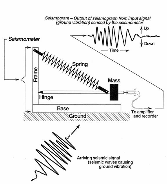
Figure 1. Schematic diagram of a seismometer. Ground motion causes the base and frame of the seismometer. The mass, suspended by the spring and boom, tends to stay in one place because of inertia. The relative motion of the base as compared to the mass is recorded as the output of the seismometer.
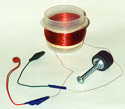
Figure 2. Photo of magnet and coil used to illustrate electromagnetic coupling used in a seismometer. A small plastic container wrapped with magnet wire (100 or more turns; place two-sided tape on the outside of the container to help hold the magnet wire) forms the coil. Solder alligator clip leads to the ends of the wire. The magnet (one or more circular magnets) is attached to a bolt for convenience in holding the magnet and moving the magnet inside the coil. For the coil assembly shown here, a 118 mL (4 oz.) container (Rubbermaid "Servin' Saver") was used. Fine gauge magnet wire was wrapped on the outside of the container. Rubber bands were used to keep the wire from unwinding.
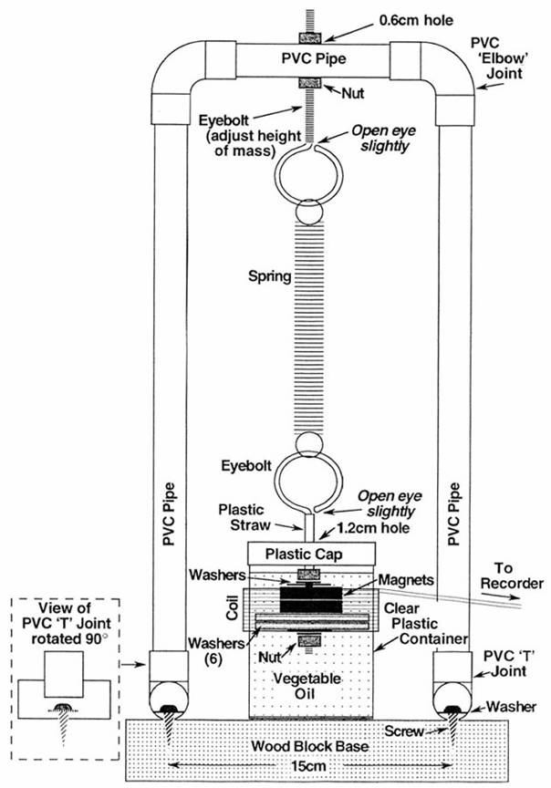
Figure 3. Diagram showing construction details for the handheld seismometer. Parts are listed in Table 1.
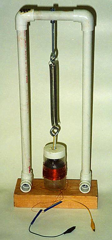
Figure 4. Photo of completed handheld seismometer.
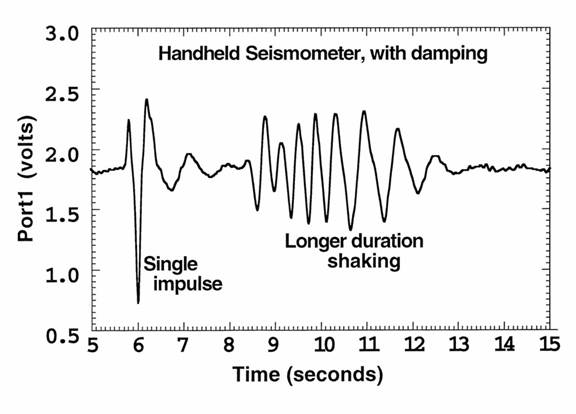
Figure 5. Sample output from the handheld seismometer using the amplifier interface circuit (see Simple Seismograph activity), Vernier software SBI interface and Logger Pro display software. The input signal (shaking of the seismometer held in one's hands) was a single impulse (one sudden upward motion of the seismometer's base) followed by a few seconds of shaking the seismometer up and down.
Figure 6. Amplifier and DC offset circuit diagram.

Figure 7. Construction details for the amplifier and DC offset circuit. Parts are listed in Table 2. Photographs illustrating the completed circuit and use of the circuit with the magnet and coil assembly are shown in Figures 8 and 9.
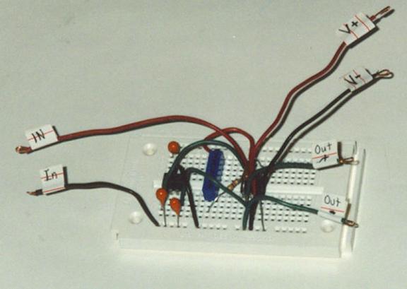
Figure 8. Close-up view of completed amplifier and DC offset circuit. Components and jumper wires are placed in the "experimenter's board" using the plans shown in Figure 7.
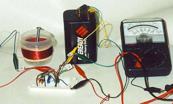
Figure 9. Photograph of amplifier circuit connected to magnet and coil assembly to provide input signal and multimeter to view output signal. A 6 volt battery is used to provide power for the amplifier circuit. Alligator clip test leads are used to connect the battery to the circuit and the output of the circuit to the multimeter. It is useful to leave the circuit uncovered and make the attachments with the test leads to illustrate the use of electronic circuits. Circuits that are similar in concept, but usually much more complicated, form the basis for the many electronic products (computers, televisions, CD players, VCRs, radios, etc.) that we use daily.