Purdue University
EAS 557
Introduction to Seismology
Robert L. Nowack
Lecture 5
Now we begin developing some of the basic concepts of continuum mechanics that we will need to study the propagation of elastic waves in the Earth. It is these elastic waves that are recorded on seismographs. The information they contain provides us with much of what we know about both earthquake sources and the structure of the Earth’s interior. So, it is important for us to understand the fundamentals if we are to properly interpret the information brought to us about the Earth’s interior by the elastic wave types we see on seismograms.
The concepts of stress and strain are fundamental to describing the force balance and geometrical description of continuous deformable bodies (like the Earth). The relation between stress and strain allows us to relate the applied forces to the resulting deformation in much the same way that the extension of a spring is related to the force pulling on it.
The particular kind of relation between stress and strain that we shall derive is called linear elasticity because the resulting strain is linearly proportional to the applied stress. So, to a high degree of precision, the Earth can be modeled as a linear elastic system over the short time span of seismic waves and, using observations of elastic waves, we can derive the elastic properties within the Earth.
Analysis of Strain
We shall consider a fixed set of axes and express all vectors and “tensors” in terms of their components with respect to these axes. First, several definitions:
A Deformable body = a body that changes shape under the action of forces (internal (like gravity) or external forces)
A Rigid (nondeformable) body = a body that undergoes only rigid motions (i.e., translations and rotations).
Deformation = strain = the change of relative position of points within the body (distortion stretch, etc.).
The assumptions on a continuum are
1) continuity of deformation (i.e., no tears or dislocations within body)
2) single valued deformation (i.e., 1-1 correspondence in strained and unstrained configuration
Consider a material in which a particle initially having
position ![]() moves to some other point
moves to some other point ![]() . We will
write
. We will
write
![]()
where ![]() is the
position and time dependent displacement.
is the
position and time dependent displacement.
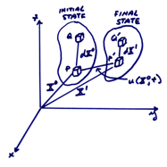
The distance between particles P and Q in the initial state
is ![]() . After
deformation, P is displaced by
. After
deformation, P is displaced by ![]() to
to ![]() and Q is
displaced to
and Q is
displaced to ![]() . Note
that we define
. Note
that we define ![]() in terms
of
in terms
of ![]() [a Lagrangian description - a function of where it comes
from], or in terms of
[a Lagrangian description - a function of where it comes
from], or in terms of ![]() [a Eularian description – a function of where the
particle is]. For infinitesimal
deformation of linear elasticity, it is simpler to use the Lagrangian
description.
[a Eularian description – a function of where the
particle is]. For infinitesimal
deformation of linear elasticity, it is simpler to use the Lagrangian
description.
The
separation between the displaced particles ![]() and
and ![]() is
is ![]() . This can
be written from the figure
. This can
be written from the figure
![]()
(1)
![]()
Now
we want to express ![]() in terms
of
in terms
of ![]() and
and ![]() . Use a
Taylor expansion of
. Use a
Taylor expansion of ![]()
![]()
where ![]() .
.
In
the vicinity of P at ![]() , we can find the changes in length of any elementary
line, segment
, we can find the changes in length of any elementary
line, segment ![]() to first
order as
to first
order as
![]()
where the summation convention over repeated indices can be used to suppress the summation sign. In vector notation,
![]() (2)
(2)
where ![]() is the
outer product,
is the
outer product,

where ![]() are the
components of the
are the
components of the ![]() displacement
vector in the figure above. This includes 9 partial derivatives and is a rank 2 tensor. A
linearized version of equation (1), in component form, can then be written as,
displacement
vector in the figure above. This includes 9 partial derivatives and is a rank 2 tensor. A
linearized version of equation (1), in component form, can then be written as,
![]() (sum
on j) (3)
(sum
on j) (3)
In
order to give a physically meaningful representation of the local deformation,
we separate ![]() into its
symmetric and antisymmetric parts. Thus,
into its
symmetric and antisymmetric parts. Thus,


In an abridged notation, let
![]()
This is the infinitesimal strain tensor which is symmetric (in the infinitesimal case, there is no distinction between Langrangian and Euclerian descriptions), and
![]()
This is the rotation tensor which is antisymmetric.
The above equation can then be written
![]()
Thus, the infinitesimal strain tensor has six independent
components, ![]() and
and ![]() , and the rotation tensor has three independent
components,
, and the rotation tensor has three independent
components, ![]() . We will
now give a physical interpretation of these components.
. We will
now give a physical interpretation of these components.
The Physical
Interpretation of Strain and Rotation
Consider first in 2-D
A) Tensional strains
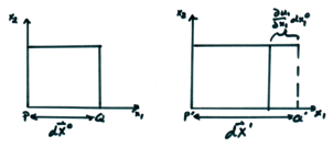
Assume only u1 exists (i.e. u2 = 0). Then, from equation (3)
![]() (sum on j)
(sum on j)
for the only non-zero component i = 1,
![]()
Since ![]() , the relative extension is
, the relative extension is
![]()
Thus, ![]() measures
the relative extension along the x1
direction. In a similar fashion,
measures
the relative extension along the x1
direction. In a similar fashion, ![]() and
and ![]() measure
the relative extensions in the x2
and x3 directions. The sign convention used here is,
measure
the relative extensions in the x2
and x3 directions. The sign convention used here is,
![]() for extension
for extension
![]() for contraction
for contraction
Also, note that strains are dimensionless.
B) Shear Strains
The
off diagonal terms, ![]() , are usually called “shear strains” because they
measure the local shearing. First,
we will look at simple shear
, are usually called “shear strains” because they
measure the local shearing. First,
we will look at simple shear
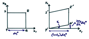
From the figure and equation (3), then
![]()
Since ![]() ,
,
![]()
Then,
![]()
and,
![]()
Now, from the figure

For small angles, ![]() (for small
shear strains). Thus,
(for small
shear strains). Thus,
![]()
and, from the equation for strain
![]()
Thus, for simple strain, e12 is just half the shearing angle.
The general shear strain case in 2-D is shown below.
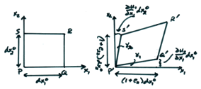
Expressing the displacements of the points Q, R, and S in terms of the displacement and its first derivatives at the point P, we can approximate
![]()
![]()
and
![]()
is the average shear angle change
between line segments PQ and PS.
Note that the approximations to use ![]() and
and ![]() require
that
require
that
![]()
In fact, we require that all the strain components be infinitesimal. This is satisfied in the Earth where maximum strains associated with elastic waves are on the order of 10-4 – 10-5. The other shear strains e13 and e23 are similarly defined with respect to the different coordinate axes.
C) Rotation
In 2-D, the rotation tensor is associated with the angle of rotation of the diagonals. For example, in 2-D
![]()
where ![]() indicates
rotation in the counterclockwise direction. Note that rotation does not necessarily
imply shear or deformation. It is
simply a local solid rotation by an angle related to
indicates
rotation in the counterclockwise direction. Note that rotation does not necessarily
imply shear or deformation. It is
simply a local solid rotation by an angle related to ![]() Referring to the diagonal
line segments from P to R and
Referring to the diagonal
line segments from P to R and ![]() to
to ![]() in the
figures above, simple shear has a non-zero rotation of the block. This is true for a general shear as
well. Pure shear has
in the
figures above, simple shear has a non-zero rotation of the block. This is true for a general shear as
well. Pure shear has ![]() resulting
in no block rotation since then
resulting
in no block rotation since then ![]() . In 3-D,
we can similarly define
. In 3-D,
we can similarly define ![]() and
and ![]() with
respect to each pair of coordinate axes.
with
respect to each pair of coordinate axes.
Dilatation
An important variable we have to
define is the relative change of volume (or area in 2-D) due to the
deformation. Consider again the 2-D
example. If the initial area of the
2-D block is ![]() , the area of the strained block is approximately
, the area of the strained block is approximately
![]()
We then define the dilatation ![]() to be
to be
![]()
where ![]() is the
divergence of the displacement field
is the
divergence of the displacement field ![]() .
.
By a similar argument, in 3-D
![]()
The dilatation (or dilation) is the relative increase of volume due to deformation and equals the sum of the diagonal elements of the strain tensor. Thus,
![]()
where ![]() is the
divergence of the displacement field.
is the
divergence of the displacement field.
As we shall see, the dilatation moves through the body at the P velocity.
Rotation
Another important variable useful in dealing with elastic waves is the rotation vector defined by
![]()
That is, the rotation vector is the curl of the displacement field.
In
3-D, the rotation vector ![]() describes
the rotation of a material element surrounding the point P. The rotation and corresponding shear strain
propagates at the velocity of shear waves (S waves) in an elastic material.
describes
the rotation of a material element surrounding the point P. The rotation and corresponding shear strain
propagates at the velocity of shear waves (S waves) in an elastic material.
An example of the static horizontal displacement field measured geodetically after the 1927 Tango, Japan earthquake is shown in Figure 1. This shows the decay of fault parallel displacement with distance perpendicular to the fault.
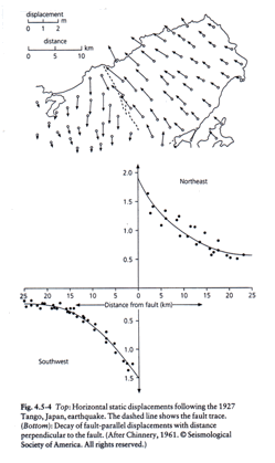
Figure 1 (from Stein and Wysession, 2003)
In the last decade, high precision GPS measurements can now attain accuracies of 10 mm in displacement and relative ground velocities of several mm/year.
Synthetic aperture radar interferometry (InSAR) uses high resolution radar mapping from spacecraft or aircraft to map the surface. By taking phase differences between images taken before and after an earthquake, very high resolution interferometric images of ground displacement can be obtained as shown in Figure 2. The top figure is a measured interferometric image of ground displacement and the bottom is from a computer model of ground displacement resulting from slip on the fault.
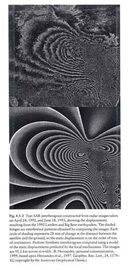
Figure 2 (from Stein and Wysession, 2003)